Numerical Investigation of Factors Influencing Oil and Gas Lifelines Behavior due to Normal Faulting Geo-Hazard
Reza Yeganeh Khaksar1 * , Majid Moradi1 and Mahsa Khorasani2
1
School of Civil Engineering, College of Engineering,
University of Tehran,
Tehran
Iran
2
College of Computer Engineering,
Iran University of Science and Technology,
Tehran
Iran
http://dx.doi.org/10.12944/CWE.10.Special-Issue1.97
In this study, some factors influencing the response of buried oil and gas lifelines subjected to normal faulting are investigated. Due to such phenomenon, the stress, strain and displacement are induced in pipeline. Finite element code of Abaqus has been employed to model pipe and its surrounding soil considering material nonlinearities, soil-pipe interaction and foot wall and hanging wall interface. The numerical model has been calibrated through some small scale geotechnical centrifuge model tests and based on such calibrated model, some factors influencing the response of buried pipeline has been investigated.
Copy the following to cite this article:
Khaksar R. Y, Moradi M, Khorasani M. Numerical Investigation of Factors Influencing Oil and Gas Lifelines Behavior due to Normal Faulting Geo-Hazard. Special Issue of Curr World Environ 2015;10(Special Issue May 2015). DOI:http://dx.doi.org/10.12944/CWE.10.Special-Issue1.97
Copy the following to cite this URL:
Khaksar R. Y, Moradi M, Khorasani M. Numerical Investigation of Factors Influencing Oil and Gas Lifelines Behavior due to Normal Faulting Geo-Hazard. Special Issue of Curr World Environ 2015;10(Special Issue May 2015). Available from: http://cwejournal.org?p=757/
Download article (pdf)
Citation Manager
Publish History
Introduction
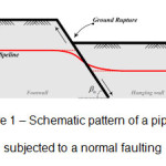
Nowadays, there are provisions and facilities in life of human being that are called lifelines regarding their vital and significant role; and mankind has always tried to maintain them even in emergencies in order to guarantee his life. Among such lifelines, the oil, gas and water pipelines are of prime importance which are usually installed in buried form. The buried pipelines usually pass through various geographical regions and thus they face numerous kinds of geotechnical hazards depending on zones passing. Earthquakes are one of the serious geotechnical hazard categories that could affect passing pipelines. Regarding seismic safety investigation, seismic hazards are classified to permanent ground deformations (PGD) and seismic wave propagations. This study focuses on normal dip-slip faulting which is categorized as a permanent ground deformation class. Faulting is the phenomenon in which a differential movement happens between two huge ground zones. Although such movement could be assumed a quasi-static manner and not necessarily a seismic one, but it could affect the pipelines structural integrity seriously and often lead to failure of the pipeline. A schematic pattern of such event is demonstrated in Fig. 1.
 |
|
Post-earthquakes studies imply that the major damages to the pipelines are caused by permanent ground deformations. PGDs affect a limited range of pipeline networks but they have a great potential for serious damages. Numerous PGD damages have been reported from all around the world such as the earthquakes of San-Francisco (1906 - USA), San Fernando (1971 - USA), Kobe (1995 - Japan), Kocaeli (1999 - Turkey) and Chi-Chi (1999 - Taiwan). The country of Iran is also facing numerous severe and weak earthquakes every year that could damage the passing lifelines. On the other hand, it has a widespread network of pipelines drawn from south to north and west to east. Comparison of national oil and gas networks with potential fault map of Iran would reveal the importance of such investigation (Fig. 2). An energy crisis may take place in the case of such happening.
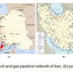 |
Figure 2: (a) national oil and gas pipeline network of Iran, (b) potential fault map of Iran Click here to View figure |
Regarding the significance of such issue, numerous studies have been conducted in order to investigate the response of pipelines subjected to faulting. Newmark and Hall (1975) were one of the first to develop a simplified analytical method for a strike-slip fault. Kennedy et al. (1977) extended the work by Newmark and Hall (1975) through considering the effects of the pipe-soil lateral interaction. Afterwards, Wang and Yeh (1985) modified a closed-form analytical model. Takada et al. (2001) proposed a simplified analytical model determining the maximum strain in steel pipelines. Furthermore, numerous numerical studies have been conducted in recent decades. Ariman and Lee (1991) employed a numerical finite element model to investigate the effects of pipe diameter, burial depth and other parameters on pipeline bending strains. Meyersohn (1991) used the Unipip finite element software ti investigate the pipeline strains. The first full-scale modeling was conducted on segmental pipes under normal faulting by Takada (1984). Liu and O'Rourke (1997) started a research sequence including analytical, numerical and physical (full-scale and geotechnical centrifuge) modelings including studies conducted by Ha et al. (2008a), Ha et al. (2008b), O'Rourke et al. (2005) and Ha et al. (2008). More recent, Rojhani et al. (2011), Rojhani et al. (2012) and Moradi et al. (2013) have done a series of centrifuge modelings of pipelines under normal and reverse faulting while the results of the latter have been implemented in current study.
Performance Criteria
For the mechanical response analysis of buried pipelines subjected to large ground deformations, stress-based design criteria are usually used. Such approach employs the minimum yield strength of pipe material as a limit load although the material, steel, is ductile and capable of undergoing significant amount of inelastic deformation. Therefore, in the case of great ground-induced deformation conditions, pipeline performance should be addressed in terms of limit states based on strain and the pipeline strain can be allowed to be more than the specified yield strain. Considering above, the following limit states could be discussed for the buried pipelines induced to normal faulting: (a) longitudinal tensile strain capacity and (b) compressive strain (local buckling formation) (Vazouras et al., 2012). On the other hands, the tensile capacity of a pipe are significantly controlled by the weakest zone of welded region and the adjacent area that is so-called "Heat Affected Zone" (HAZ). The efficient factors influencing the joints performance are: (a) less ductility of the HAZ pipe material, (b) welding faults in slips and joints, and (c) pipeline coating corrosion potential. Therefore, the suggested design strain is considered just a fraction of material tensile capacity. Based on standards and codes (Nyman, 1984; Eurocode, 1998; ASCE MOP, 2009), the conservative strain limit of 3% could be considered as design limit for pipelines and welded areas in normal operability. On the other hand, normal faulting displacements could cause compressive strains in some specific conditions which would result in buckling. The compressive strain limit for pipes is far less than tensile values and are proposed in form of pipeline mechanical and geometrical properties functions.
Numerical Modeling
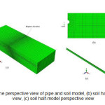
In presented study, the factors influencing the pipeline response subjected to normal faulting are investigated, using the finite element approach of Abaqus (Hibbitt et al., 2011). Such mechanism has a three dimensional characteristic so the modeling has been conducted in three dimensional form. In order to decrease the computation costs, a half model has been considered due to the x-y symmetric plane (Fig. 3).
 |
|
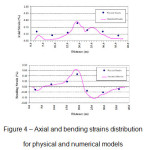
Regarding the physical modeling limitations of parameter varying difficulties, such models could not cover a wide range of physical, mechanical and geometrical elements properties. In this case, the calibrated numerical models could assist significantly. In calibration process, the model parameters are chosen, through related tests (e.g. direct shear test), in a way that the model output shows the minimum error compared to physical model results. Here, three physical centrifuge model results by Moradi et al. (2013) have been considered as calibration basis. The calibration is conducted through an artificial intelligence framework (Gen and Cheng, 2000; Ravindran et al., 2006; Chambers, 1998) which is not discussed here. In such approach, the soil-pipe interaction, soil and pipe constitutive laws and joints properties have been considered as optimization parameters. The other numerical properties such as geometrical specifications are set according to the physical models. The results of one centrifuge test have been compared with the calibrated numerical model ones, as depicted in Fig. 4. According to the comparison, there is a good and convincing fitness between the two types of models, considering the errors included in a physical modeling approach.
 |
|
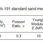
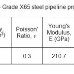
In current study, the constitutive models of elastoplastic Mohr-Coulomb with isotropic strain softening and isotropic hardening has been considered for surrounding soil (Firoozkouh 191 Standard Sand) and Steel pipeline (API 5L X65), respectively, in a nonlinear quasi-static analysis approach. such mechanical properties are indicated in Tab.1 and 2.
 |
|
 |
|
Soil-pipe interaction is introduced through a Coulomb friction coefficient of (μ) with the value of 0.44 (Yimsiri et al., 2004). The analysis is run in two steps. In the first step the geostatic loads have been applied and the rupture displacement is subjected in the second step. The model parameters design is based on the values employed and common in engineering practices. Therefore, the pipe diameter of 0.25m to 1.25 m, the burial depth of 0.6m to 1.2m and the diameter to wall thickness ratio of 50 to 150 have been picked up for the parametric study (O'Rourke and Liu, 1999; API, 1999; IPLOCA, 2013) in which the influencing factors on pipe response have been specified.
Numerical Results and Discussion
In this section, the numerical results of the base (core) model has been presented initially and through a conducted parametric study, the effect of some variables have been discussed then.
Core Model Results
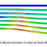
The faulting and failure evolution in the core model with the pipe diameter of 1.25m, pipe wall thickness of 25mm, burial depth of 0.9m and faulting angle of 60º are demonstrated in Fig. 5.
 |
|
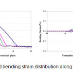
General investigation of the results show that contrary to strike-slip faults, the passive resistance could not be considered uniform along the pipe length in the normal faulting. Therefore, the affected length (Le) of pipe is much longer in the normal faulting than the strike-slip one. Also, the pipe behavior reveals that the longitudinal component of displacement is dominant in the very first steps of deformation. As the faulting movement increases, the transverse (normal) component of displacement is affecting the pipeline behavior till reaching the critical displacement (Ucr) in which the pipeline experiences the failure criterion. The investigation shows that the tensile axial behavior of the pipe dominates the bending one and the axial strains are significantly bigger than the bending ones.
 |
|
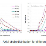
The effect of Burial Depth
To investigate the effect of changes in burial depth, the analysis is conducted for the burial depths of 0.6m and 1.2m while keeping other variables equal and fixed. Regarding the dominant axial behavior of the pipe, the distribution of axial strain is depicted in Fig. 7.
 |
|
Change of burial depth demonstrates that in shallower burial depth, the axial strain values would be lower due to the overburden reduction and vice versa. On the other hand, burial depth reduction would increase the fault affected length (Le) of pipe. This seems more apparent in bigger faulting offset magnitudes.
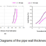
The effect of Pipe Wall Thickness
The pipe wall thickness reduction from 25mm (D/t = 50) to 8.3mm (D/t = 150) would decrease the affected length of pipe, while keeping the pipe diameter fixed (Fig. 9(a)). In other words, the thicker pipelines would experience longer affected lengths due to bigger values of section inertia moment. Also, pipes with thinner walls would reach the failure strains in lower offset values (Fig. 9(b)).
 |
|
Critical Fault Displacement
As a numerical modeling privilege, the fault offset is not limited to an specified value and the displacement is continued till the pipe experiences tensile failure criterion. The critical displacements for all studied models are included in Table. 3. Such results show that
Table 3: Critical fault displacements for the models
|
Tensile failure Strain Criterion |
Critical Fault Offset |
Difference from core model |
Model No. |
|
3% |
2.76 m |
--- |
Model 1 (Core) |
|
3% |
4.64 m |
Depth reduction to 0.6m |
Model 2 |
|
3% |
2.14 m |
Depth increase to 1.2m |
Model 3 |
|
3% |
1.77 m |
Pipe wall thickness reduction to 8.3mm |
Model 4 |
The results show that the burial depth reduction would increase the offset bearing capacity of the pipeline. In other words, the shallow buried pipeline could tolerate bigger magnitudes of fault offset while burial depth increasing would decrease the offset bearing capacity of pipe. Also, the pipe wall thickness reduction would make the pipeline more sensitive to displacement. Apart from mentioned parameters, some other ones have also been investigated that are not discussed here.
Conclusion
In this study, the factors influencing the behavior of oil and gas lifelines due to normal faulting are numerically investigated. Such numerical model is developed, calibrated and extended based on some small scale geotechnical centrifuge tests. Then, a parametric study has been conducted to study some geometrical and physical parameters effects on pipeline response. The results of such investigation could be as follow:
- The affected length of pipeline in normal faulting is much longer than the same condition in the strike-slip faulting.
- The dominant behavior of the pipe is axial and the pipeline meets the tensile failure criterion.
- The burial depth increase would decrease the affected length of pipe while intensifying the strain magnitudes.
- Pipe wall thickness reduction would decrease the affected length and critical failure offset.
- The increase of the fault offset would cause bigger values of strain in deep buried and thin wall pipelines.
Acknowledgement
This article presents a part studies conducted through a Ph.D. thesis in geotechnical engineering, in School of Civil Engineering, University of Tehran, Iran. All experts are gratefully acknowledged.
References
- American Petroleum Institute. Pipeline Segment, & CSS Info. Design, construction, operation, and maintenance of offshore hydrocarbon pipelines. American Petroleum Institute (1999).
- ASCE manual of practice (MOP). Buried flexible steel pipe; design and structural analysis. p. 119. (American Society of Civil Engineers, 2009).
- Ariman, T; Lee, B. J. Tension Bending Behavior of Buried Pipelines Under Large Ground Deformations in Active Faults. Lifeline Earthquake Engineering. 226-233(1991).
- Chambers, L. D. Practical handbook of genetic algorithms: complex coding systems(Vol. 3). (CRC press, 1998).
- Silos, Tanks and Pipelines Annex A. Eurocode, 8, Part 4. CEN ENV (1998).
- Gen, M; Cheng, R. Genetic algorithms and engineering optimization. (John Wiley & Sons, 2000).
- Ha, D; Abdoun, T. H; O'Rourke, M. J; Symans, M. D; O'Rourke, T. D; Palmer, M. C; Stewart, H. E. Buried high-density polyethylene pipelines subjected to normal and strike-slip faulting-a centrifuge investigation. Canadian Geotechnical Journal,45(12), 1733-1742 (2008a).
- Ha, D; Abdoun, T. H; O'Rourke, M. J; Symans, M. D; O'Rourke, T. D; Palmer, M. C; Stewart, H. E. Centrifuge modeling of permanent ground deformation effect on buried HDPE pipelines.Journal of Geotechnical and Geo environmental Engineering, 134(10), 1501-1515 (2008b).
- Hibbitt, H; Karlsson, B; Sorensen, P. Abaqus Analysis User’s Manual Version 6.10. Dassault Systèmes Simulia Corp.: Providence, RI, USA (2011).
- IPLOCA document. THE ROAD TO SUCCESS Vol. 1 & 2, 3rd edition. (September 2013).
- Kennedy, R. P; Chow, A. M; Williamson, R. A. Fault movement effects on buried oil pipeline.Transportation engineering journal of the American Society of Civil Engineers, 103(5), 617-633 (1977).
- Liu, X; O'Rourke, M. J. Behaviour of continuous pipeline subject to transverse PGD.Earthquake engineering & structural dynamics, 26(10), 989-1003 (1997).
- Manfredi, C; Otegui, J. L. Failures by SCC in buried pipelines. Engineering Failure Analysis,9(5), 495-509 (2002).
- Meyersohn, W. D. Analytical and design considerations for the seismic response of buried piplines. Cornell University (1991).
- Moradi, M; Rojhani, M; Galandarzadeh, A; Takada, S. Centrifuge modeling of buried continuous pipelines subjected to normal faulting. Earthquake Engineering and Engineering Vibration,12(1), 155-164 (2013).
- Newmark, N. M; Hall, W. J. Pipeline design to resist large fault displacement. (1975).
- Nyman, D. J. Guidelines for the seismic design of oil and gas pipeline systems. Americal Society of Civil Engineering, (1984).
- O'Rourke, M. J; Liu, X. Response of buried pipelines subject to earthquake effects. (1999).
- O'Rourke, M; Gadicherla, V; Abdoun, T. Centrifuge modeling of PGD response of buried pipe.Earthquake Engineering and Engineering Vibration, 4(1), 69-73(2005).
- Ravindran, A; Reklaitis, G. V; Ragsdell, K. M. Engineering optimization: methods and applications. (John Wiley & Sons, 2006).
- Rojhani, M. Moradi, M. Galandarzadeh, A. Takada, S. Centrifuge modeling of buried pipelines response due to normal faulting. 14th Asian Regional Conference on Soil Mechanics and Geotechnical Engineering, Hong Kong, China. Paper 188, 2011.
- Rojhani, M; Moradi, M; Galandarzadeh, A; Takada, S. Centrifuge modeling of buried continuous pipelines subjected to reverse faulting.Canadian Geotechnical Journal, 49(6), 659-670 (2012).
- Takada, S. Model analysis and experimental study on mechanical behavior of buried ductile iron pipeline subjected to large ground deformation. 8th World Conference on Earthquake Engineering, July,V 7, 255-262 (1984).
- Takada, S; Hassani, N; Fukuda, K. A new proposal for simplified design of buried steel pipes crossing active faults.Earthquake engineering & structural dynamics, 30(8), 1243-1257 (2001).
- Vazouras, P; Karamanos, S. A; Dakoulas, P. Mechanical behavior of buried steel pipes crossing active strike-slip faults.Soil Dynamics and Earthquake Engineering, 41, 164-180 (2012).
- Wang, L. R. L; Yeh, Y. H. A refined seismic analysis and design of buried pipeline for fault movement.Earthquake engineering & structural dynamics, 13(1), 75-96 (1985).
- Yimsiri, S; Soga, K; Yoshizaki, K; Dasari, G. R; O'Rourke, T. D. Lateral and upward soil-pipeline interactions in sand for deep embedment conditions. Journal of geotechnical and geoenvironmental engineering, 130(8), 830-842 (2004).